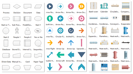

They are merely used to represent a certain type of component. It is important to note that these symbols are NOT to scale and are NOT dimensionally accurate. There are standard symbols used to represent the components in these diagrams. P&IDs also are used as the basis for the live graphic representation of a process system in its HMI (human-machine interface) or other control system. Maintenance and modification to the system.

Employee training of process system operation.Startup, shutdown, and operating schemes and procedures.Installation and/or build-out of the system.Safety and operational analysis (HAZOP – hazard and operability study).As such, the P&ID is crucial in all stages of process system development and operation. The P&ID is the primary schematic drawing used for laying out a process control system’s installation. in different colors to show the status of the device.A piping and instrumentation diagram (P&ID) is a graphic representation of a process system that includes the piping, vessels, control valves, instrumentation, and other process components and equipment in the system. For example signal towers ('traffic light') or a motor/fan/pump/. Under "Toolbox > Graphics > WinCC Graphics Folder > Unified and modular" you can find several graphics which you can use in a graphics list to indicate different statuses of objects/proecesses.

What controls do you think of if you say "process indicators"? > See chapter "Increase Clarity" > Gauge Controls for Basic Panels You can't use the "normal" gauge-control on a Basic Panel, but here is a version you can use: Master copies > Design_4 > D4_Control_4.


 0 kommentar(er)
